- Cisco Community
- Technology and Support
- DevNet Hub
- DevNet Data Center
- Controllers
- PNP Switch Error tftp
- Subscribe to RSS Feed
- Mark Topic as New
- Mark Topic as Read
- Float this Topic for Current User
- Bookmark
- Subscribe
- Mute
- Printer Friendly Page
PNP Switch Error tftp
- Mark as New
- Bookmark
- Subscribe
- Mute
- Subscribe to RSS Feed
- Permalink
- Report Inappropriate Content
12-29-2016 09:42 AM - edited 03-01-2019 04:35 AM
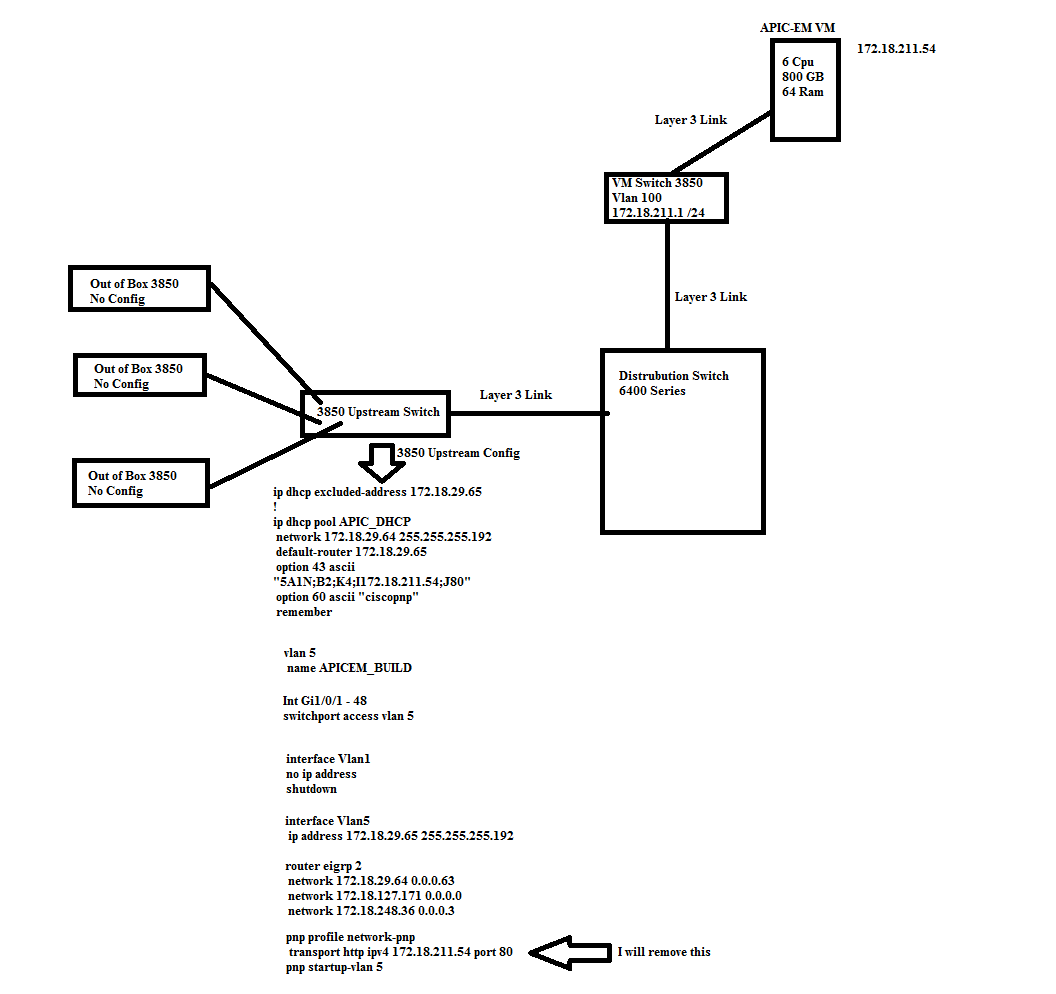
So I have a 3850-48P connected to my my upstream switch that has local DHCP and pnp profile created. The upstream switch is also a 3850 switch. Here is my pnp and dhcp settings just for verification.
ip dhcp pool APIC_DHCP
network 172.18.29.64 255.255.255.192
default-router 172.18.29.65
option 43 ascii "5A1N;B2;K4;I172.18.211.54;J80"
option 60 ascii "ciscopnp"
remember
pnp profile network-pnp
transport https ipv4 172.18.211.54 port 443
The switch that is getting connected to the upstream switch gets connected to APIC-EM and says deploying config and so far the status for deploying config has not changed, but with a console cable the switch shows the following.
Would you like to enter the initial configuration dialog? [yes/no]:
%Error opening tftp://255.255.255.255/network-confg (Timed out)
%Error opening tftp://255.255.255.255/cisconet.cfg (Timed out)
%Error opening tftp://255.255.255.255/router-confg (Timed out)
%Error opening tftp://255.255.255.255/ciscortr.cfg (Timed out)
I can hit enter and answer no to the initial configuration dialog, and I can see that the switch did instead pull the config from APIC-EM. But status still shows deploying config. On the switch that is getting configured I do have the following showing up.
Dec 29 12:37:23: %DUAL-6-NBRINFO: EIGRP-IPv4 2: Neighbor 172.18.29.65 (Vlan100) is blocked: not on common subnet (172.18.45.1/24) with 172.18.45.1 being the new data subnet on the switch that received the config file from APIC-EM.
Anything wrong with my configurations for DHCP or any other steps I might have missed?
- Labels:
-
APIC
- Mark as New
- Bookmark
- Subscribe
- Mute
- Subscribe to RSS Feed
- Permalink
- Report Inappropriate Content
12-29-2016 10:05 AM
I have a question. Why are you using both the DHCP option and PnP profile?
Thanks
- Mark as New
- Bookmark
- Subscribe
- Mute
- Subscribe to RSS Feed
- Permalink
- Report Inappropriate Content
12-29-2016 10:11 AM
Nicholas,
I thought I needed to have both? If not can I just use PNP profile on my upstream switch and remove dhcp?
- Mark as New
- Bookmark
- Subscribe
- Mute
- Subscribe to RSS Feed
- Permalink
- Report Inappropriate Content
12-29-2016 10:23 AM
You should not need both. Give it a try with the PnP profile. Ensure the device has no other configuration.
no pnp profile pnp-zero-touch
no crypto pki certificate pool
delete vlan.dat (for Switch devices)
clear capwap private-config (for Wireless AP devices)
delete /force nvram:*.cer
delete /force stby-nvram:*.cer (for HA system)
write erase
reload
- Mark as New
- Bookmark
- Subscribe
- Mute
- Subscribe to RSS Feed
- Permalink
- Report Inappropriate Content
12-29-2016 11:57 PM
Hi Jason.
Thanks for all the information. A couple of points:
1) Your DHCP settings are fine.
2) You do not need the pnp profile. That should be setup automatically by DHCP discovery.
3) There seems to be an issue with the configuration you are pushing to the device. This is the most common cause of a config being pushed, but contact being lost to the controller.
4) The tftp error messages can be ignored.
To troubleshoot further, we would need to understand a bit more about the topology/configuration you are pushing.
A couple of questions:
1) Is vlan 100 the management vlan, and how did this get created?
2) What was the vlan that was used to run PnP?
Adam
- Mark as New
- Bookmark
- Subscribe
- Mute
- Subscribe to RSS Feed
- Permalink
- Report Inappropriate Content
12-30-2016 07:04 AM
Adam,
I have attached my design sorry for using paint lol. To answer your questions, Vlan 100 is the data subnet for clients and that is configured for the config being pushed by APIC-EM. So I have a fully written config just as if I was going to copy and paste it into the console for a out of the box switch. Once the out of the box gets the config and the interface I was using to patch into the upstream switch gets put into vlan 100, hence the eigrp issue. I'm using vlan 5 on the upstream switch for building the out of the box switches with an ip address of the gateway of the internal DHCP server on the switch. I'm sure i'm missing a concept here, and appreciate any direction you guys can give. Thanks for the replies.
- Mark as New
- Bookmark
- Subscribe
- Mute
- Subscribe to RSS Feed
- Permalink
- Report Inappropriate Content
12-31-2016 08:43 PM
Thank Jason,
this is helpful.
On the upstream switch, you only need the "pnp startup-vlan 5" command. (as you have identified)
The "pnp profile ...." commands will be created automatically via the DHCP discovery process on the "out of the box" switches.
The issue you are seeing is due to the way you are using vlans. Can you explain a little more about why you are using vlan 100 and vlan 5?
From your diagram, is the distribution switch a "6400" or "6500"?
I am not sure those interfaces are really L3 interfaces between the switches?
Can you share the configuration on the interfaces between 3850 upstream switch and the "6400"?
Adam
Discover and save your favorite ideas. Come back to expert answers, step-by-step guides, recent topics, and more.
New here? Get started with these tips. How to use Community New member guide